|
|
|
|||||||||||
|
Contact: Mail |
|
|||||||||||
|
The Prototype Märklin-H0-Knowledge Layout-Building Modelstock |
|
|||||||||||
|
Circuits
for advanced users – Automation of Processes The relatives of the Märklin universal remote switches |
|
|||||||||||
|
state: 13.02.2026 12:12 |
|
|||||||||||
|
It is important in many circuits: the universal
remote switch - that's what Märklin calls this bistable relay. A
relay is an electrically operated switch that is switched over by one or two
electric solenoids. There
are two operating principles: o
Monostable: one coil activates the switch and a spring resets it when
the control voltage is removed. o
Bistable: one coil activates the switch and a second coil resets it.
Both positions are stable thanks to mechanical measures and, depending on the
design, may also be resistant to vibrations. Why is a bistable relay important? Sometimes you want to fix a
switching state on your model railway layout for a longer period of time –
just as turnouts and signals remain in their position when you pull the power
plug. Bistable relays used to be similar
in design to turnout and signal drives. Today, there are also electronic
means of maintaining a switching state permanently without a power supply. Märklin is, of course, not the only
manufacturer that builds (or built) such devices. In this article, I present a number
of alternative bistable relays, some with special features. If you know of any other products,
please let me know. Common features As a rule, bistable relays have two
solenoids that pull an armature back and forth, thus realizing two switching
positions. Note: The connection is therefore usually
made with an AC power supply from the transformer connection “L” and two
control lines for the two switching positions, which are briefly
(!) supplied with a voltage pulse from the transformer connection
“0”. The relays are equipped with
different working contacts. Some relays have an integrated limit
switch. This means that the duration of the control signal is irrelevant for
them. An overview |
|
|||||||||||
|
Manufacturer |
Number |
Contacts |
Connections |
Special feature |
|
|||||||
|
Märklin |
7045 |
1x CO |
model railway connector |
|
|
|||||||
|
Märklin |
7245 |
1x CO + 2x NC/NO |
plugs and terminals |
|
|
|||||||
|
Märklin |
7244 |
4x CO |
terminals |
continuous voltage resistant |
|
|||||||
|
Faller |
649 |
2x NC/NO |
plugs |
|
|
|||||||
|
Eheim |
TRV |
2x NC/NO |
plugs |
two functional variants |
|
|||||||
|
Trix Express |
6590 |
1x CO |
terminals |
|
|
|||||||
|
Trix Express |
6591 |
4x CO |
terminals |
|
|
|||||||
|
Trix Express |
6592 |
2x CO |
terminals |
end switch |
|
|||||||
|
BTTB/Tillig |
8410 |
2x CO |
terminals |
|
|
|||||||
|
Piko |
--- |
1x CO |
terminals |
end switch |
|
|||||||
|
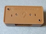
Fleiscmann |
6956 |
2x CO |
terminals |
|
|
|||||||
|
Roco |
10019 |
4x CO |
spec. plugs / |
end switch |
|
|||||||
|
Viessmann |
5551 |
4x CO |
plugs |
|
|
|||||||
|
Viessmann |
5552 |
2x 2 CO |
plugs |
two relays in one housing |
|
|||||||
|
Hongfa |
HFD2 … L2 |
2x CO |
soldering |
continuous voltage resistant (?) |
|
|||||||
|
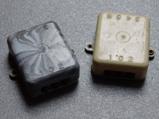
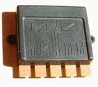
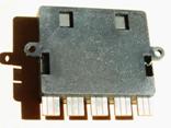
The “universal remote switches” from
Märklin. Märklin designed signals without displays
in parallel with the signal types. UFS 7045 looked like the drive units
of the 70xx series signals, double solenoid coil. UFS 7245 looked like the drive units
of the 72xx series signals, double solenoid coil. UFS 7244 is a fully electronic
development independent of other products. |
|
|||||||||||
|
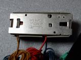
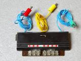
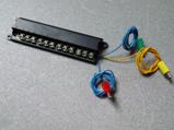
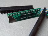
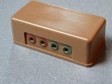
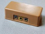
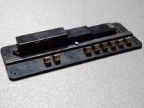
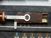
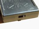
Märklin 7045 is no longer manufactured and is only available second-hand. Märklin
7045 has 6 connections: Märklin
7045 has a changeover switch. Connection
and function: The
yellow wire to “L” on the transformer (16V AC), the
blue wires with red and green plugs can be connected briefly
(!) to ground “0” on the transformer to activate the coils, NO
limit switch, the
red wire is connected alternately to one of the sockets. Märklin
7045 has a manual switch lever. |
|
|||||||||||
|
|
||||||||||||
|
|
|
|||||||||||
|
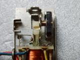
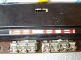
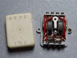
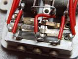
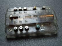
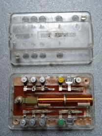
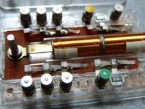
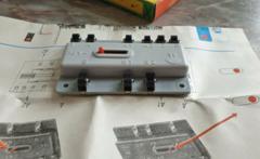
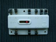
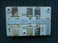
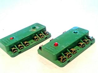
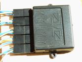
Märklin 7245 is no longer manufactured and is only available second-hand. Märklin
7245 has 10 connections: Märklin
7245 has 1 changeover switch/selector switch and 2 normally open/normally
closed contacts. Connection
and function: The
yellow wire to “L” of the transformer (16V AC), the
blue wires with red and green plugs, optionally activated briefly (!) to ground “0” of the transformer, activated
the coils, NO limit switch. Changeover/switch
from terminal 2 to terminals 1 or 3, normally
open/normally closed between terminals 4 and 5 Märklin
7245 has a manual switch lever. This
relay is known to be unreliable. |
|
|
|||||||||||
|
|
|
||||||||||||
|
|
|
|||||||||||
|
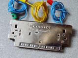
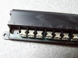
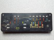
Märklin 7244 has 15 connections: Märklin 7244 has 4 changeover
switches/switches. Connection and function: The yellow wire connected to “L” on
the transformer (16V AC), the blue wires with red and green
plugs, optionally also for longer periods (!) to ground “0” of the
transformer, activate the switchover. Changeover/switch from terminal 2 to
terminals 1 or 3, Märklin 7244 has no manual control
option. |
|
|||||||||||
|
|
||||||||||||
|
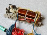
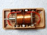
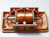
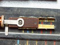
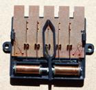
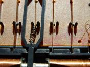
The Faller No. 649 switching relay Two powerful coils work inside this
relay. The armature is centered in each
coil and connects two contact springs with its pin-shaped ends. |
|
|||||||||||
|
Faller 649 is no longer manufactured and is only available second-hand. Faller
649 has 7 connections: 7 labeled sockets. Faller
649 has 2 NO/NC contacts. Connection
and function: Yellow
socket “0” to “L” of the transformer (16V AC), blue
sockets “x” and ‘y’ optionally activate the switchover briefly
(!) to ground “0” of the transformer, NO limit switch. Pulse at socket “x” disconnects the
red sockets ‘3’ and “4” pulse at socket “y” disconnects the
green sockets ‘1’ and “2” Faller
649 has no manual control option. |
|
|||||||||||
|
|
||||||||||||
|
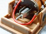
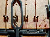
The EHEIM TRV switching relay This relay was originally designed
to control the EHEIM overhead bus (trolleybus). The accompanying instructions
describe only such applications. The armature is designed as a finger
that is mounted on a pivot point and is alternately attracted by the two
coils. The finger connects two pairs of
contact springs in each switching position. The EHEIM TRV is no longer
manufactured and is only available second-hand. The Eheim TRV has 8 connections: There are 2 ways to connect the
Eheim TRV. The EHEIM TRV does not have a manual
control option. |
|
|||||||||||
|
Variant 1: Connection
exclusively to the sockets: In
this connection type, the EHEIM TRV has 1 normally closed contact and 1
normally open contact. Connection
and function: Socket
“0” to “L” of the transformer (16V AC), sockets
“1” and ‘2’ optionally activate the switchover briefly(!)
to ground “0” of the transformer, NO limit switch. Pulse at socket “1” disconnects
sockets ‘3’ and “4” Pulse at socket “2” disconnects
sockets ‘5’ and “6” |
|
|||||||||||
|
Variant 2: Connection
to the sockets and to the contact on the mounting hole: In
this connection type, the EHEIM TRV has 2 normally closed contacts and 2 normally
open contacts with a common input. Connection
and function: Socket
“0” to “L” of the transformer (16V AC), Sockets
“1” and ‘2’ optionally briefly(!) to
ground “0” of the transformer Connection
“M” to input signal. Pulse at socket “1” disconnects
sockets “3” and “4” from ‘M’ Pulse at socket “2” disconnects
sockets “1” and “2” from ‘M’ |
|
|||||||||||
|
|
||||||||||||
|
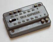
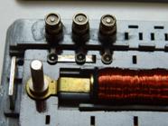
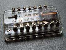
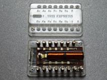
The TRIX-EXPRESS relays The TRIX-EXPRESS relays are no
longer manufactured and are only available second-hand. There were three versions of a
bistable relay: No. 6590 with one
changeover/changeover switch and WITHOUT limit switch, ATTENTION: Officially, the coils are designed
for 14V AC! The housings were available in gray
and transparent. |
|
|||||||||||
|
The TRIX-EXPRESS 6590 has 6 labeled
connection terminals. The TRIX-EXPRESS 6590 has 1 changeover switch/selector switch. Connection and function: Terminal “0” to “L” of the transformer with voltage reduction to 14V
AC, terminals “1” and ‘2’ optionally briefly(!) to
ground “0” of the transformer Pulse at terminal “1” switches terminal A0 to terminal A1, pulse at terminal “2” switches terminal A0 to terminal A2. The TRIX-EXPRESS 6590 has a manual switch lever. |
|
|||||||||||
|
|
||||||||||||
|
|
|
|||||||||||
|
The
TRIX-EXPRESS 6591 has 15 labeled
connection terminals. The
TRIX-EXPRESS 6591 has 4 changeover/switching contacts. Connection
and function: Terminal
“0” to “L” of the transformer with voltage reduction to 14V AC, Terminals
“1” and ‘2’ optionally briefly(!) to
ground “0” of the transformer Pulse at terminal “1” switches terminal A0 to terminal A1, pulse at terminal “2” switches terminal A0 to terminal A2, The
TRIX-EXPRESS 6591 has a manual switch lever. |
|
|||||||||||
|
|
||||||||||||
|
|
|
|||||||||||
|
The
TRIX-EXPRESS 6592 has 9 labeled connection
terminals. The
TRIX-EXPRESS 6592 has 2 changeover switches/switches. Connection
and function: Terminal
“0” to “L” of the transformer with voltage reduction to 14V AC, Terminals
“1” and “2” optionally connected to ground “0” of the transformer – also for
longer periods (!) – activate the switchover. After
switchover, the relay automatically removes the voltage from the coil; WITH
end switch! Pulse at terminal “1” switches terminal A0 to terminal A1, Pulse at terminal “2” switches terminal A0 to terminal A2, The
TRIX-EXPRESS 6592 has a manual switch lever. |
|
|||||||||||
|
|
||||||||||||
|
The 8410 switching relay from
Berliner TT Bahnen or Tillig |
|
|||||||||||
|
The
8410 switching relay is probably no
longer manufactured and can only be obtained second-hand. The
8410 switching relay has 9 labeled connection terminals. The
8410 switching relay has 2 changeover/changeover switches. Connection
and function: Terminal
“R” to “L” of the transformer (16V AC), Terminals
“1” and “2” optionally activate the switchover briefly
(!) to ground “0” of the transformer, NO end switch. Pulse at terminal “1” switches terminal A to terminal A1, Pulse at terminal “2” switches terminal A to terminal A2, The
8410 switching relay has a manual switch lever. |
|
|||||||||||
|
|
||||||||||||
|
The PIKO relay |
|
|||||||||||
|
The
PIKO relay is no longer manufactured and is only available second-hand. The
PIKO relay has 8 connection terminals without labeling. The
numbers in the circuit diagram correspond to the following diagram:
The PIKO relay has 1 changeover
contact/changeover switch. Connection and function: Terminal 3 to “L” of the transformer
(16V AC), terminals 1 and 2 optionally – even
for longer periods (!) – to ground “0” of the transformer activate the
changeover; WITH end switch. A position signal can be tapped at
terminals 4 and 5. A pulse at terminal 1
switches terminal 8 to terminal 6 and A pulse at terminal 2
switches terminal 8 to terminal 7 and The PIKO relay has a manual switch
lever. |
|
|||||||||||
|
|
||||||||||||
|
Fleischmann Universal Relay 6956 I do not own this relay, so the information
provided is only speculation based on its external appearance. |
|
|||||||||||
|
The
Fleischmann Universal Relay 6956 is
no longer manufactured and is only available second-hand. The
Fleischmann Universal Relay 6956 has 9 labeled connection terminals. The
Fleischmann Universal Relay 6956 apparently has 2 changeover
contacts/switches. Connection
and function: Presumably
terminal “B” to “L” of the transformer with voltage reduction to 12 to 14V AC
(presumably AC, because that is/was generally customary), presumably
terminals “A” and ‘C’ selectively activate the switchover, probably briefly(!), to ground “0” of the transformer, A
pulse at terminal “A” or alternatively “C” presumably switches terminal 2 to
terminal 1 or 3 and terminal 5 to terminal 4 or 6. The
Fleischmann 6956 relay has two manual switch buttons. |
vermutlicher
Schaltplan
|
|||||||||||
|
|
||||||||||||
|
Roco changeover relay 10019 |
|
|||||||||||
|
The
Roco changeover relay has 5 connection tongues, each with 3 contact surfaces,
i.e. 15 connections, without labeling. Roco
offers the 3-pin connector 10603 for connecting 3 wires each = connection of
a switch. However, you can also solder to the contact surfaces. The
numbers in the circuit diagram correspond to the following drawing, view of
the top side with the circuit diagram:
The Roco changeover relay has 4 changeover
contacts/switches. Connection and function: Contact surface “X0” to “L” of the
transformer (16V AC), contact surfaces “X1” and ‘X2’
optionally – even for longer periods (!) – to ground “0” of the transformer
activate the changeover; WITH end switch. Pulse at contact surface “X1”
switches Pulse at contact surface “X2”
switches The Roco changeover relay has a
manual switch lever. |
|
|||||||||||
|
|
||||||||||||
|
Viessmann universal relay I do not own this relay, so the
information is only speculation based on its external appearance. |
|
|||||||||||
|
The
Viessmann universal relay 5551 has 15
connection sockets without labeling. The
Viessmann universal relay 5551 has 4 changeover contacts/switches. The
numbers in the circuit diagram correspond to the following illustration, view
of the top side with the circuit diagram:
Connection and function: Socket “0” to “L” of the transformer
with 16V AC, Sockets “1” and ‘2’ optionally
activate the switchover briefly (!)
to ground “0” of the transformer, NO limit switch. Pulse at socket “1” switches socket
A0 to socket A1, socket B0 to socket B1, socket C0 to socket C1, and socket
D0 to socket D1. pulse at socket “2” switches socket
A0 to socket A2, socket B0 to socket B2, socket C0 to socket C2, and socket
D0 to socket D2. The Viessmann universal relay 5551
has a manual switch lever. |
|
|||||||||||
|
|
|
|||||||||||
|
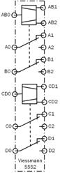
The
Viessmann universal relay 5552 has 18
connection sockets without labeling. The
Viessmann universal relay 5552 contains 2 relays, each with 2 changeover
contacts/switches. The
numbers in the circuit diagram correspond to the following illustration, view
of the top side with the circuit diagram:
Connection and function: Sockets “AB0” and ‘CD0’ connected to
“L” of the transformer with 16V AC, Sockets “AB1” and “AB2” or “CD1” and
‘CD2’ optionally activated briefly(!) to
ground “0” of the transformer activate the switchover, NO limit switch. Pulse at socket “AB1” switches
socket A0 to socket A1, socket B0 to socket B1, Pulse at socket “AB2” switches
socket A0 to socket A2, socket B0 to socket B2. A pulse at socket “CD1” switches
socket C0 to socket C1, socket D0 to socket D1. A pulse at socket “CD2” switches
socket C0 to socket C2, socket D0 to socket D2. The Viessmann universal relay 5552
apparently has no manual override. |
|
|||||||||||
|
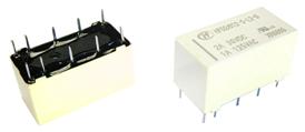
HongFa HFD2 … L2 Printed Circuit
Relay These relays are designed for printed
circuit board mounting. They have solder tabs with a 2.54 mm pitch. The type we need has two pairs of
connection tabs for actuation, i.e., one pair of connections for switching to
position I and one pair of connections for switching to position II. There are types for 12V DC and also
for 5V DC and 24V DC, which means that DC voltage is required with a
different voltage than that supplied by the Märklin transformers at the “L”
connection. One option would be to use an old Märklin speed controller set to
12 V, for example, and connect a rectifier to “B” and “0”. Alternatively, a
speed controller from the DC world could be used, or a new power supply unit
from an electronics retailer. The big advantage of these relays is
that they are much cheaper than electromechanical ones. However, you need to
be able to solder to connect them to the wires. With circuit board material
and connection terminals, the price advantage is soon lost. However, complex control systems
become small and inexpensive. |
|
|||||||||||
|
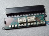
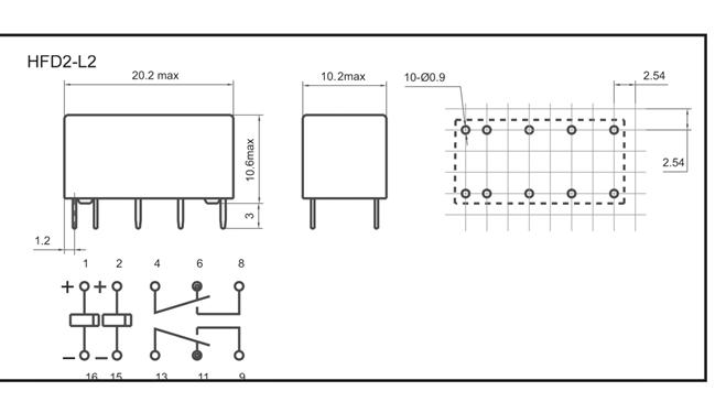
The
HongFa HFD2 has 10 solder tabs in a 2.54 mm = 1/10 inch grid. The
HongFa HFD2 has 2 changeover switches/selectors. The
HongFa HFD2 is available for 12V DC and 5V DC operating voltage. Connection
and function: Connections
15 and 16 to the negative terminal of the DC transformer. A
connection 1 and 2 optionally to the positive terminal of the transformer –
also for longer periods – activates the switchover. A
pulse at connection 1 switches A
pulse at connection 2 switches |
|
|||||||||||
|
|
|
|||||||||||
|
|
|
|||||||||||
|
There are other print relays on the
market. |
|
|||||||||||
|
|
|
|||||||||||
|
The Prototype Märklin-H0-Knowledge Layout-Building Modelstock |
|
|||||||||||