|
|
|
|||||||||||||||||||||
|
Contact: Mail |
|
|||||||||||||||||||||
|
The Prototype Märklin-H0-Knowledge Layout-Building Modelstock |
|
|||||||||||||||||||||
|
The very first
basic knowlege about conventionally controlled Märklin H0 model railways The
evolution of Märklin command and switch panels |
|
|||||||||||||||||||||
|
state: 10.02.2026 15:12 |
|
|||||||||||||||||||||
|
Preliminary remarks Sometimes I repeat
things to complete the section. Designation of
connections: “0” connection is the brown connection on the Märklin
transformer (there may be duplicate, then both are equivalent), “L”
connection is yellow, “B” connection is red. Since I only have
few of the devices described below, I use images from the catalogs that are
published here or in my archive are. Sensible
previous knowledge: Functionality and connection of the Märklin turnouts and
signals as well as the uncoupling track section, solenoid devices. Each solenoid has a
yellow connection cable that is connected to the yellow socket/terminal
"L" on the transformer. Every by solenoid
driven unit has o
one (uncoupling
track) or o
two (simple
turnouts, two-aspect signals) or o
three (three-aspect
signals) or o
four (three-way
turnout) blue
connection line(s) to which ground from connection "0" of the
transformer must be connected for a short moment via a momentary contact so
that the circuit for the coil is closed and the movement takes place. The contact element
of a momentary contact command panel
transmits a voltage as long as the finger exerts pressure on the actuating
element. The contact element
of a permanent contact switch panel
maintains the current position of the switching element. For those in a hurry, an overview
... Momentary
contact command panels |
|
|||||||||||||||||||||
|
numbers |
catalog years |
purpose |
picture |
|||||||||||||||||||
|
472 |
1936
– 1947 |
for
2 single solenoids |
|
|||||||||||||||||||
|
473/6 |
1936
– 1947 |
for
6 single solenoids |
|
|||||||||||||||||||
|
473/12 |
1937
– 1939 |
for
12 single solenoids |
|
|||||||||||||||||||
|
474/4 |
1949
– 1952 |
for
4 single solenoids |
|
|||||||||||||||||||
|
474/8
B |
1949
– 1952 |
for
8 single solenoids |
|
|||||||||||||||||||
|
476/4 |
1953
– 1956 |
for
4 double solenoids |
|
|||||||||||||||||||
|
7271 |
1994
– 2004 |
for 4 turnout drives of
K or C-track |
|
|||||||||||||||||||
|
7272 |
1995
– 2004 |
for
4 double solenoids |
|
|||||||||||||||||||
|
72710 |
since
2005 |
for 4 turnout drives of
K or C-track |
|
|||||||||||||||||||
|
72720 |
since
2005 |
for
4 double solenoids |
|
|||||||||||||||||||
|
70729 |
2010
– 2017 |
for
4 double solenoids |
|
|||||||||||||||||||
|
72751 |
since
2011 |
for
4 signals |
|
|||||||||||||||||||
|
72752 |
since
2011 |
for 4 turnout drives of
C-track |
|
|||||||||||||||||||
|
permanent
contact switch panels |
|
|||||||||||||||||||||
|
numbers |
catalog years |
purpose |
picture |
|||||||||||||||||||
|
494 |
before
1936 - ? |
1
switch |
|
|||||||||||||||||||
|
475/4 |
1950
– 1956 |
4
switches with common input |
|
|||||||||||||||||||
|
474/6 |
1955
–1956 |
4
separate switches |
|
|||||||||||||||||||
|
7210 |
1962
– 1994 |
4
switches with common input |
|
|||||||||||||||||||
|
7211 |
1962
– 1994 |
4
separate switches |
|
|||||||||||||||||||
|
7273 |
1995
– 2004 |
4
switches with common input |
|
|||||||||||||||||||
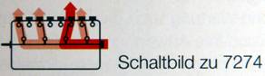
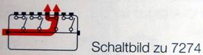
|
7274 |
1995
– 2004 |
4
separate switches |
|
|||||||||||||||||||
|
72730 |
since
2005 |
4
switches with common input |
|
|||||||||||||||||||
|
72740 |
since
2005 |
4
separate switches |
|
|||||||||||||||||||
|
72750 |
since
2005 |
Signal switch panel for
the Hobby-signals 74391, 74380 and 74371 |
|
|||||||||||||||||||
|
72751 |
since
2011 |
for
4 digital signals |
|
|||||||||||||||||||
|
72760 |
since 2013 |
for 4 digital signals |
|
|||||||||||||||||||
|
70739 |
since 2010 |
4 switches with common
input |
|
|||||||||||||||||||
|
70749 |
2010-2021 |
4 separate switches |
|
|||||||||||||||||||
|
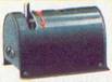
From the beginning It
all began in 1935 when Märklin created its first electric 00 gauge model
railroad. Märklin manufactured
electromagnetically operated turnouts and signals earlier for gauges 0 and 1.
Similar to this
TRIX Express turnout: |
|
|||||||||||||||||||||
|
|
|
|||||||||||||||||||||
|
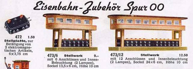
The 1936 catalog
showed the following momentary contact
command devices (sorry, only german):
|
||||||||||||||||||||||
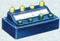
|
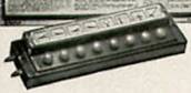
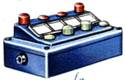
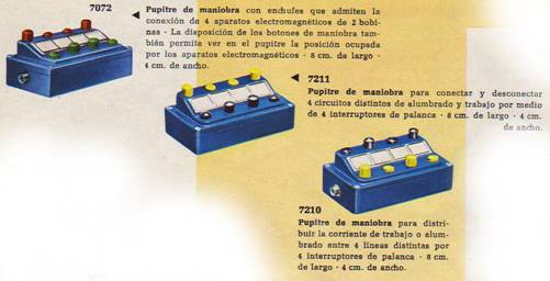
The „Stellplatte
472“ can be plugged together to form larger control
units. We see two plug
connections per button. A double line was led from the setting contact to the
solenoid, so - compared to today's technology - the light line (today yellow,
from the transformer connection "L") and the ground line (today
blue, via the setting contact from the transformer connection "0"). It should therefore
be possible to integrate these control devices into our more modern system. Stellplatte 472 in
catalogs from 1936 to 1947. Stellwerk 473/6 in
catalogs from 1936 to 1947. Stellwerk 473/12 in catalogs from
1937 to 1939. |
|
|||||||||||||||||||||
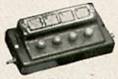
|
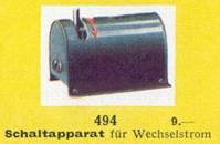
The „Schaltapparat
494“ could be described as a permanent
contact switch apparatus. Found in the catalog 1936 to 1938. |
|
|
||||||||||||||||||||
|
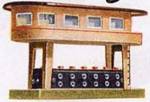
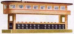
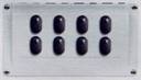
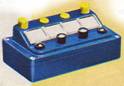
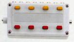
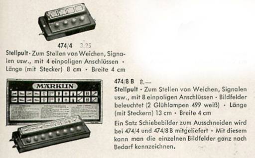
In
1949 these momentary contact command panels
appeared.
Amazingly, the image
fields on the 8-way control console were illuminated! The consoles had a
plug on the narrow left side and a sleeve on the narrow right side for
connection to the ground connection "0" on the transformer. The
control lines for the solenoid accessories were then connected to the rear.
The 8-button console had further connections for the supply of lighting on
the narrow sides. Stellpult 474/4 in
the catalog from 1949 to 1952. Stellpult 474/8 B in
the catalog from 1949 to 1952. These units can be
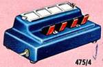
plugged together to form larger control units. A permanent contact switch panel was not listed in 1949, but
the new crane released that year already included the control panel 475/4,
which was offered separately first in 1950. |
|
|||||||||||||||||||||
|
|
|
|||||||||||||||||||||
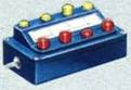
|
The position of the
connections is the same as for the 4-way control desk 474/4. On the narrow sides
there are plugs on the left and sockets on the right for connecting the
voltage that is to be switched. On the back there are 4 sockets assigned to
the levers. These
switch panels can be plugged together to form larger switching units. This switch panel
is particularly suitable for lighting because you can only transmit one
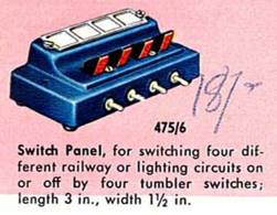
voltage. Several consoles are required for different voltages. Switch panel 475/4 in the catalog from 1950 to 1956, |
|
|||||||||||||||||||||
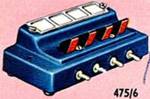
|
In 1955, Märklin
remedied the lack of requiring separate switch panels for different voltages
and released the switch panel 475/6 with 4 separate current paths. Here are the 4
inputs with plugs at the front and the assigned 4 outputs with sockets at the
rear. |
|
|
||||||||||||||||||||
|
switch
panel 475/6 in the catalog from 1955 to
1956, A new generation of
momentary contact „Control plate“ with
plastic housings started in 1953 with no. 476/4. |
|
|||||||||||||||||||||
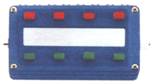
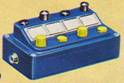
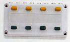
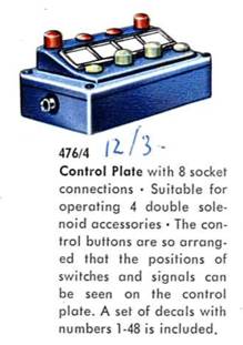
|
This control plate
has 4 pairs of momentary contacts and is therefore intended for 4 solenoid
items with double coil drives. The ground
connection is designed as a socket on the left narrow side and as a plug on
the right narrow side. The control plates can be plugged together to form
larger command units. control plate 476/4
mit
no 7072 |
|
|
||||||||||||||||||||
|
Note from the author: I could never get familiar with
the philosophy of these control plates. If you connect a signal
according to the instructions and in the correct color, i.e. the control line
with the red plug to the red socket and the control line with the green plug
to the green socket, the operation is the other way around as expected. When you press the red button,
the green button comes up and the signal turns green. Green signal, green button up,
that's what Märklin thought. Green signal, green button up,
that's what Märklin thought. But pressing the red button so
that the signal turns green is strange ... In 1955 the crane
got a new control panel, a combination of 2 pairs of momentary contacts for
turning and lifting/lowering and 2 switches, one of which is intended for the
magnet and the light. |
|
|||||||||||||||||||||
|
|
|
|||||||||||||||||||||
|
This heralded the
new generation of permanent contact switch
panels, but it wasn't until 1962.
button colours
1962 |
|
|||||||||||||||||||||
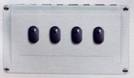
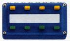
|
The switch panel 7210
with the common input on the left as a plug and on the right as a socket has
4 outputs at the rear. In the first year the inputs are still swapped and
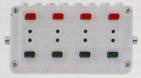
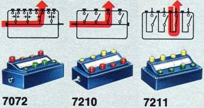
thus like the control plate 7072. The switch panels
7210 can be plugged together to form larger switch units. The yellow buttons
on the front switch on, the black buttons on the back switch off. The control panel
7211 has 4 separate contact paths, therefore 8 sockets at the rear. Black buttons on
the front and yellow buttons on the back. The switching function should have
been the same. |
|
|||||||||||||||||||||
|
The colors of the
buttons were changed in 1963. |
|
|
||||||||||||||||||||
|
switch panel 7210
in the catalog from 1962 to 1994 switch panel 7211
in the catalog from 1962 to 1994 In 1994 a new generation
came, the penultimate one. White plastic and square buttons. The first control
plate was a special one, only suitable for the turnout drives of the K track
and later also the C track and with LEDs for feedback. |
|
|||||||||||||||||||||
|
|
||||||||||||||||||||||
|
The successors to
the blue control plates and switch panels followed in 1995. The control plate
for 4 double solenoid drives: |
|
|||||||||||||||||||||
|
|
||||||||||||||||||||||
|
The control plates 7272
can be plugged together to form larger control units. The switch panel
with 4 separate contact paths: |
|
|||||||||||||||||||||
|
|
||||||||||||||||||||||
|
The switch panel
with 4 contacts with a common input: |
|
|||||||||||||||||||||
|
|
||||||||||||||||||||||
|
The 7274 switch
panels can be plugged together to form larger switch
units. |
|
|||||||||||||||||||||
|
The control panel
7274 had 4 changeover switches in the first year, at
least that's what the catalog says. I don't know whether that was really the
case. That made this first series something special. |
only 1995
|
|
||||||||||||||||||||
|
As early as the
second year of the catalog, the control panels only had 4 simple NO / NC
contacts, each with two sockets at the output. Outwardly, the control panels
did not change. |
from 1996
|
|
||||||||||||||||||||
|
control plate 7271 in the catalog from
1994 to 2004 control plate 7272 in the catalog from
1995 to 2004 switch panel 7273 in the catalog from
1995 to 2004 switch panel 7274 in the catalog from
1995 to 2005 New connector
system In 2005 a new
connector system was introduced in accordance with the current safety
regulations. |
|
|||||||||||||||||||||
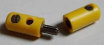
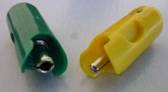
|
Old plugs
|
New plugs
|
|
||||||||||||||||||||
|
This changed all connections. Control plate 7271 became control
plate 72710. Control plate 7272 became control
plate 72720. Switch panel 7273 became switch
panel 72730. Switch panel 7274 became switch
panel 72740. |
|
|||||||||||||||||||||
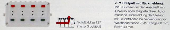
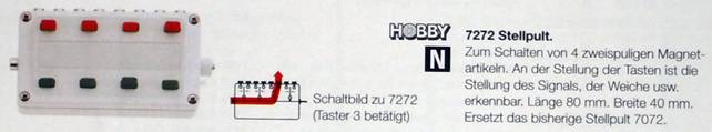
|
And the signal
switch panel 72750 for the hobby signals 74391, 74380 and 74371 was created. This panel has
completely different plug connections. Switch panel 72750 |
|
|
||||||||||||||||||||
|
In 2010 Märklin
realised that the new plug system was not generally accepted, that there was
still a need for control plates and switch panels with the old connections. Therefore, blue
ones with old sockets, diameter 2.6 mm, appeared again: |
|
|||||||||||||||||||||
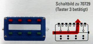
|
control plate
70729, |
|
|
||||||||||||||||||||
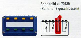
|
switch panel 70739,
|
|
|
||||||||||||||||||||
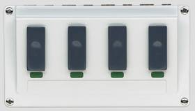
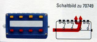
|
switch panel 70749,
|
|
|
||||||||||||||||||||
|
In 2011 appeared
new control plates/switch panels for digital signals and C track turnout
drives: |
|
|||||||||||||||||||||
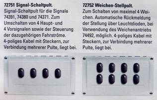
|
signal switch panel
72751, turnout control
plate 72752, |
|
|
||||||||||||||||||||
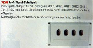
|
signal switch panel
72760, |
|
|
||||||||||||||||||||
|
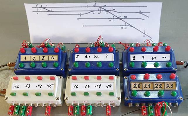
A tip for installing
the control panels A member of my
German group showed the following picture: |
|
|||||||||||||||||||||
|
|
|
|||||||||||||||||||||
|
I mentioned several
times above that the panels can be plugged together. Here you can see that
you can also combine the older blue panels (7072) with the newer white panels
(7272). The special trick
in this picture, however, is that the lower parts of the panels can be turned
around and the panels are closer together. The symmetrical design of the
panels means that they can be turned around without any loss of
functionality. This does not work with control panels with LED feedback! Special control
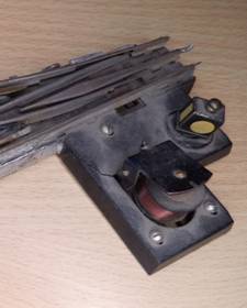
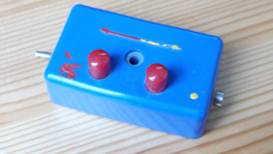
panels I have already
shown the control panel for the 7051 crane
above. The control panel
for the 7186 turntable is based on the same
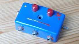
mechanical ideas as the panels of the blue generation. This box combines a
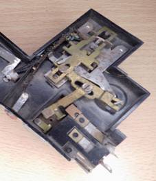
switch and a momentary contact. (Painted by my father in the 60th.) Pressing a button
moves the switch in the relevant direction and at the end of the button
stroke the contact for starting the engine is reached. |
|
|||||||||||||||||||||
|
|
|
|||||||||||||||||||||
|
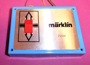
The
control panel for the 7294 transfer table
probably works (I don't have one) similar to the control panel for the
turntable. A
slide determines the direction and there is probably a momentary contact to
start the motor at the end of the switch travel.
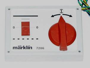
The
control panel of the 7286 turntable
has a rotary knob as a direction selector and a slide for different travel
levels.
Have
I forgotten a conventional control panel? |
|
|||||||||||||||||||||
|
The Prototype Märklin-H0-Knowledge Layout-Building Modelstock |
|
|||||||||||||||||||||