|
|
|
|||||||||||||||||||||||||||||||||||||||||||||||||||||||||||||||||||||||||||||
|
Contact: Mail |
|
|||||||||||||||||||||||||||||||||||||||||||||||||||||||||||||||||||||||||||||
|
The Prototype Märklin-H0-Knowledge Layout-Building Modelstock |
|
|||||||||||||||||||||||||||||||||||||||||||||||||||||||||||||||||||||||||||||
|
Special knowledge about tracks Märklin
“Modellgleis” (model track) |
|
|||||||||||||||||||||||||||||||||||||||||||||||||||||||||||||||||||||||||||||
|
state: 10.02.2026 17:14 |
|
|||||||||||||||||||||||||||||||||||||||||||||||||||||||||||||||||||||||||||||
|
Modellgleis? What is that? The German „Modellgleis“
means „model track“. But the „Märklin-Modellgleis“ is really something
special. There is a reason, that
so many people pay Let’s look, what is so special and whether it is
worth to go for a hunt… Vocabulary: How it started… Until 1953 Märklin
delivered only tinplate tracks with a third center rail as conductor. Then Märklin presented a
new track, the „Modellgleis“, a quantum leap in track construction. Unter the following link you find a
very good German description, that I’m quoting here: |
|
|||||||||||||||||||||||||||||||||||||||||||||||||||||||||||||||||||||||||||||
|
The „Modellgleis 3900“,
made as metal-plasic-mixed construction.
1953
the Märklin „Modellgleis“ saw the light of day. The
development of the track, probably espacially the plasic-injection molding
technology, took place in collaboration with the french model railway producer
Vollon et Brun, who offered similar tracks as the Märklin standart track on
the French as well the international market. The
„Modellgleis“ represented a technical revolution in four ways: 1. The center conductor as continuous
third rail had been replaced by point contacts for the first time. 2. The Track was made as
metal-plastic-mixed construction. The
plasic sleepers were embedded in the metal bedding. The balast bed is mottled
beige-brown, embossed and painted. The sleepers are colored black. 3. The geometry of the previous
track was abandoned and in particular two new, large radii, R4 and R5
compared with later systems, have been introduced. 4. The turnouts of this system
with a large radius and a flat branch angle of approx. 17 degrees were
designed as slim turnouts. The 17 degrees correspond to ¾ of the 22.5 degrees
standard curve track of the „Modellgleis“ system.
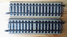
„Modellgleis 3900“
Comparsion of
„Modellgleis 3900“ and „M-track 5100“.
Comparsion of „Modellgleis 3900“ and „M-track 5100“, bedding underside. Both
the enormous space requirements of this track geometry at a time when small
„table top" tracks were still the measure of all things, as well as the
significantly higher price compared to the standard track still included in
the range (Price example 1955: Two and a half times as expensive, -, 60
pfennigs the straight 3600 standard track at 1.50 marks for the straight 3900
„Modellgleis“, which was due to the complex production and patent / license
costs to Vollon et Brun as a development partner) made the „Modellgleis“
unsuccessful, so it was disappeared from the catalog in 1957. Only in the
present is it a sought-after, rare and high-priced product on the collector's
market. Quote
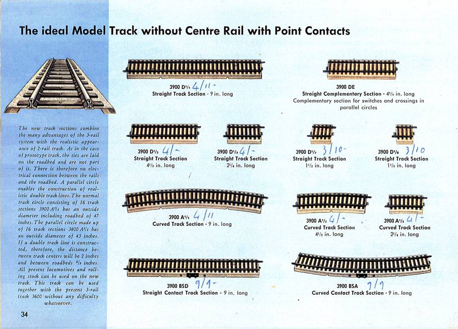
from the 1955 catalog for the „Modellgleis“: „These „Modellgleise“ combine the advantages of the 3-rail track with the
model appearance of the 2-rail track. As in the 1:1 railway, the sleepers are
separate parts, separate from the rest of the rail bed. Realistic track
layout design by parallel circle. [...] The 3600 track sections can be used
together with the 3900 „Modellgleis“ sections
without any difficulty." The
system comprised 2 radii (R4 and R5), straight tracks, contact tracks, the
slim, electrically driven turnouts and a matching crossing. As in the later
C-Track system, the slender turnouts are combined with fitting pieces for the
corresponding position depending on the track plan. The embankment of these
„Modellgleis” fittings is accordingly not at a 45 degree angle in the contact
areas, but rather straight. The
previous 180 mm geometry was abandoned and the standard length of the
straight track is 224 mm for the „Modellgleis”. The curved tracks were
implemented as 22.5 degree pieces, so that 16 track pieces form a full
circle. A
connection with the standard tracks is possible and was expressly mentioned
in the catalog.
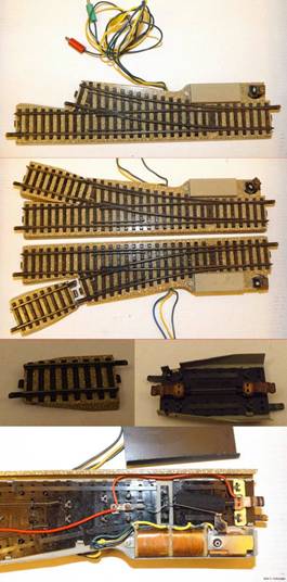
„Modellgleis“ electric
turnout 3900 MW. The
electric turnouts had an illuminated turnout lantern. Despite the relatively short
production period, parallel to the development of the „M-Track 5100-5200”,
modifications of the turnout lanterns and turnout drives can be found in the
image documents for the „Modellgleis”. The
switch technology changes in parallel from that of the 3600 track to that of
the 5100 track, although the first switch lanterns of the „Modellgleis” were
significantly smaller than those of the 3600 track. This
range is referred to as „Modellgleis”
or „Modellgleis 3900”. |
|
|||||||||||||||||||||||||||||||||||||||||||||||||||||||||||||||||||||||||||||
|
Quote End What
pieces of track were there? Note: The table below the quoted report is
difficult to read in this reproduction, contains errors and is incomplete.
Therefore I write the table of the tracks available at the time myself. First we look into the
catalog of 1953: |
|
|||||||||||||||||||||||||||||||||||||||||||||||||||||||||||||||||||||||||||||
|
|
||||||||||||||||||||||||||||||||||||||||||||||||||||||||||||||||||||||||||||||
|
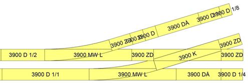
Straight pieces of
track
|
|
|||||||||||||||||||||||||||||||||||||||||||||||||||||||||||||||||||||||||||||
|
Note: The straight supplementary track section is
referred to as 3900 DÅ in the track planning program SCARM, which I’m using
for the graphics here. The visible difference
between 3900 DE and 3900 D 1/2 is a 3 mm wider sleeper spacing on half of the
3 mm longer track section. |
|
|
||||||||||||||||||||||||||||||||||||||||||||||||||||||||||||||||||||||||||||
|
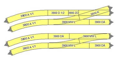
The benefits of the
complementary track section can be seen in the following track plans:
At a track connection
with two turnouts or a turnout and a crossing, it ensures that both tracks
end in one line. |
|
|||||||||||||||||||||||||||||||||||||||||||||||||||||||||||||||||||||||||||||
|
Track curves
|
|
|||||||||||||||||||||||||||||||||||||||||||||||||||||||||||||||||||||||||||||
|
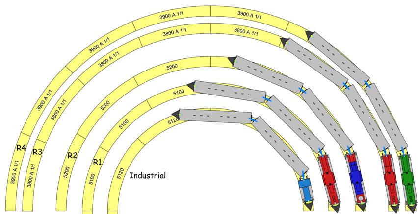
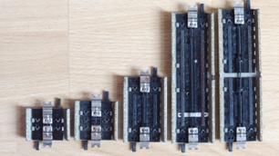
Curves 3800 and 3900 are significantly larger than those of the M
track. The curve angle of the 1/1
curve is 22.5°, therefore 8 pieces of track are
required for a semicircle. The following track plan
shows the proportions. For illustration I have
put a couple of short four-axle passenger wagons on top. |
|
|||||||||||||||||||||||||||||||||||||||||||||||||||||||||||||||||||||||||||||
|
|
|
|||||||||||||||||||||||||||||||||||||||||||||||||||||||||||||||||||||||||||||
|
The article cited above
speaks of R4 and R5. I am talking more about R3+ and R4+. Next the comparison with
the C-Track (green) and the K-Track (blue): |
|
|||||||||||||||||||||||||||||||||||||||||||||||||||||||||||||||||||||||||||||
|
|
|
|||||||||||||||||||||||||||||||||||||||||||||||||||||||||||||||||||||||||||||
|
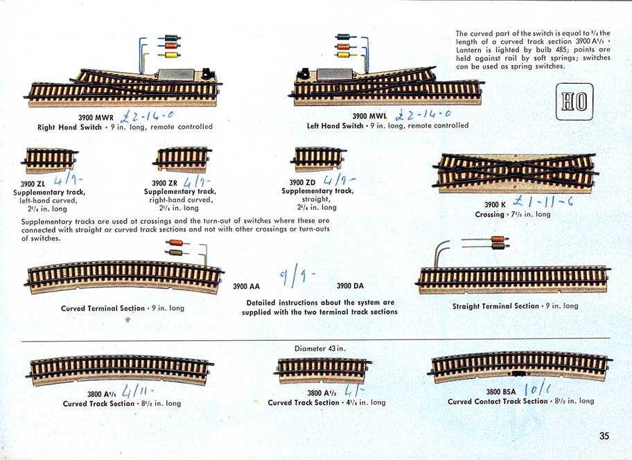
Turnouts, Crossing and accessories
|
|
|||||||||||||||||||||||||||||||||||||||||||||||||||||||||||||||||||||||||||||
|
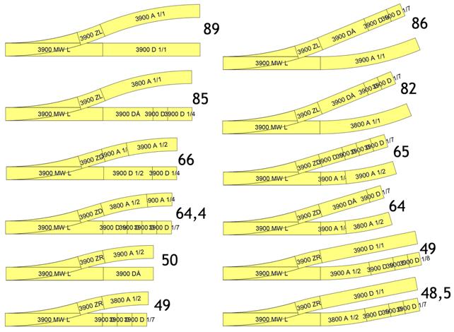
The turnouts have the same radius (585 mm) as the curves with 3900
numbers, but only 3/4 of this arc angle of the 1/1 curve (which is 22.5°). The
branch ends so early that no normal section of track will fit. There are 3 additional
pieces of track available for this purpose: The left turnout can be
supplemented with the additional track section ZL to 22.5° and the right with
ZR. You can also use the
original angle of 16.875° with the additional straight track section ZD. And - this is
interesting - you can put a left additional track section on the right
turnout or a right one on the left turnout. This reduces the turnout angle to
11.25°. However, there is a very slight winding movement of the train when
driving over it. If you attach the
opposite curve directly to the switch or the additional track section without
an intermediate straight piece of track, these track distances (in mm) result
with the various combinations: |
|
|||||||||||||||||||||||||||||||||||||||||||||||||||||||||||||||||||||||||||||
|
|
|
|||||||||||||||||||||||||||||||||||||||||||||||||||||||||||||||||||||||||||||
|
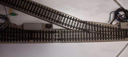
If two turnouts are to follow one
after the other in the same direction, a compensating track section must be
inserted between them because the drive box is in the way. In the first picture, there is an
additional track section ZR on the branching leg of the right turnout, so the
curve is supplemented in the same direction to 22.5°. At least one 16 mm
compensating track piece is required between the turnouts here. Note: Since the rail fishplates on
the model tracks are significantly longer than those on the M tracks, the
fishplates may need to be shortened, at least in this application. You can
clearly see that the compensating track piece cannot be inserted correctly, leaving
gaps on both sides.
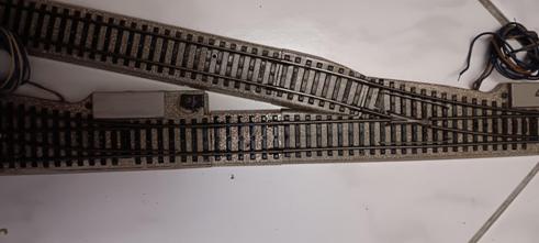
In the second picture, there is an
additional track section ZL on the diverging leg of the right-hand turnout,
i.e., a counter curve that reduces the turnout angle to 11.25°. At least one
45 mm compensation track section is required between the turnouts here.
|
|
|||||||||||||||||||||||||||||||||||||||||||||||||||||||||||||||||||||||||||||
|
The crossing is used to
cross the neighboring track, for example at a branch or a siding. That's why
it has the same angle as the turnouts.
Here you can see the restriction imposed
by the compulsory use of the additional track sections: An additional piece of track must
always be inserted at the branch of the turnout and at the track ends of the
crossing.
TIP: With manual dexterity you can certainly also adapt the
bedding of other tracks. |
|
|||||||||||||||||||||||||||||||||||||||||||||||||||||||||||||||||||||||||||||
|
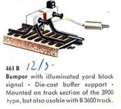
The Bumper It was the first time that a bumper
of this design appeared in the Märklin range. The basis was the straight 1/4 track
section 3900 D 1/4. |
|
|
||||||||||||||||||||||||||||||||||||||||||||||||||||||||||||||||||||||||||||
|
|
|
|||||||||||||||||||||||||||||||||||||||||||||||||||||||||||||||||||||||||||||
|
And now let's take a closer look ... |
|
|||||||||||||||||||||||||||||||||||||||||||||||||||||||||||||||||||||||||||||
|
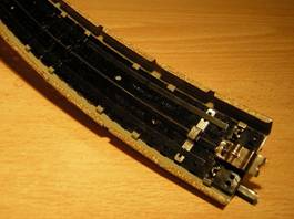
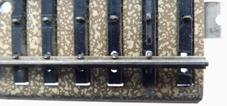
First we consider the complex basic
construction. The sheet metal ballast bed has an
opening for each sleeper. |
|
|
||||||||||||||||||||||||||||||||||||||||||||||||||||||||||||||||||||||||||||
|
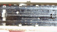
The sleepers are part of a plastic
insert that is held in the bed from below with bent sheet metal tabs. |
|
|
||||||||||||||||||||||||||||||||||||||||||||||||||||||||||||||||||||||||||||
|
The 1/1 track sections (straight as
well as arches) have 2 inserts, each with half the track section length. This
will probably have production-related reasons and stock-economy reasons. The
1/1 and 1/2 track sections have the same inserts.
|
|
|||||||||||||||||||||||||||||||||||||||||||||||||||||||||||||||||||||||||||||
|
The straight 1/4, 1/7 and 1/8 track sections
have their own inserts. The supplementary track section 3900 DE has 2 inserts
of the 1/4 track section. |
|
|
||||||||||||||||||||||||||||||||||||||||||||||||||||||||||||||||||||||||||||
|
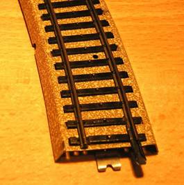
The hollow profile rails (the
switches have full profile) lie on top of the sleepers. |
|
|
||||||||||||||||||||||||||||||||||||||||||||||||||||||||||||||||||||||||||||
|
They are held in place by bent metal
noses that protrude from below through the sleepers. The noses are part of a
continuous metal band that lies on the underside of the insert. Each rail is isolated from the other
and from the track structure. |
|
|
||||||||||||||||||||||||||||||||||||||||||||||||||||||||||||||||||||||||||||
|
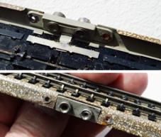
The rails are not attached to the
last sleeper because there is the connecting strap on one rail and the space
for the connecting strap of the rail to be attached to the other. |
|
|||||||||||||||||||||||||||||||||||||||||||||||||||||||||||||||||||||||||||||
|
A stronger claw is attached to the
penultimate sill, presumably to absorb the increased forces when sticking
together. |
|
|
||||||||||||||||||||||||||||||||||||||||||||||||||||||||||||||||||||||||||||
|
With many pieces of track there is a
metal bridge between the rails, so that both rails are then electrically
connected. |
|
|
||||||||||||||||||||||||||||||||||||||||||||||||||||||||||||||||||||||||||||
|
The bridge is not set to all track
sections. There are two generations - I will come back to this when describing
the center conductor. The first generation have no bridge with the exception
of the connecting and contact tracks, the second generation not always. With
arches of the 3800 form, I sometimes find the bridge at the other end. The 1/4 (straight tracks and curved
tracks), 1/7 and 1/8 track sections as well as the straight supplementary
track sections 3900 DE and the additional track sections 3900 ZD, ZL and ZR
generally do not have a bridge. This bridge can be found in the
C Track today. |
|
|||||||||||||||||||||||||||||||||||||||||||||||||||||||||||||||||||||||||||||
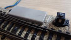
|
On the terminal track sections, the
bridge is the connection point for the earth cable. |
|
|
||||||||||||||||||||||||||||||||||||||||||||||||||||||||||||||||||||||||||||
|
There are bridges at both ends of
the contact track. |
|
|
||||||||||||||||||||||||||||||||||||||||||||||||||||||||||||||||||||||||||||
|
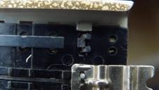
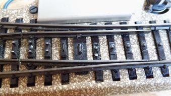
A rail is cut in two places and the
metal band is parallel to it on the underside. This creates a piece of rail
that has no electrical connection to the rest of the track. |
|
|
||||||||||||||||||||||||||||||||||||||||||||||||||||||||||||||||||||||||||||
|
In the middle of the insulated rail section,
a connector with 2 sockets is inserted into the track. The sockets are
connected to the insulated rail section. |
|
|
||||||||||||||||||||||||||||||||||||||||||||||||||||||||||||||||||||||||||||
|
TIP: You can also turn a normal piece of track into a piece
of contact track: You cut through the bridge, if it is present at all. Then
you solder a connection line to one of the rails and replace the connecting
brackets on this rail and on the subsequent rail with
insulating rail connectors that are available from Fleischmann (No. 6403 or
6433) and Roco (No. 42611). Done! |
|
|||||||||||||||||||||||||||||||||||||||||||||||||||||||||||||||||||||||||||||
|
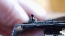
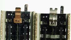
As mentioned, there are two
generations of the „Modellgleis“. The primary characteristic is the type
of center conductor connecting tongue. The first generation has small
copper tongues, the second generation wide and slightly longer nickel-plated
tongues. |
|
|
||||||||||||||||||||||||||||||||||||||||||||||||||||||||||||||||||||||||||||
|
Note: When assembling our M-rails, you can first bring
the middle conductor tongues into the desired overlap before threading the
rail brackets. The copper tongues of the „Modellgleise“ are so short and the rail brackets so long that you
first have to thread in the rail brackets and then you can only determine the
top-bottom position of the copper tongues with problems. The nickel-plated tongues of the second
generation are longer and significantly more stable than the copper tongues.
This means that they can be plugged together as we are used to. |
|
|||||||||||||||||||||||||||||||||||||||||||||||||||||||||||||||||||||||||||||
|
|
|
|||||||||||||||||||||||||||||||||||||||||||||||||||||||||||||||||||||||||||||
|
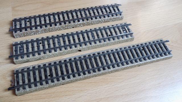
If you visually compare the M-rails with the
„Modellgleis“, you will notice that the point contacts of the „Modellgleis“ are much less conspicuous. The sleepers are nicer, the
surface uninterrupted. The optics of the M-track between 1956 and 1981
(center) were significantly worse. Only the version from 1982 (above) came
closer to the appearance of the „Modellgleis“. That is why I only use the
upper version in the visible area and „Modellgleise“ or
my M-Flex-track in the arches. The central conductor is a steel
comb that extends in one piece from the first to the last sleeper. |
|
|||||||||||||||||||||||||||||||||||||||||||||||||||||||||||||||||||||||||||||
|
In relation to the plastic insert or
the two inserts, the second and penultimate puko noses are missing. At these
points Puko inserts are let into the sleepers from above, which have lugs on the
underside with which the Puko comb is attached. Track sections with two
plastic inserts therefore have 4 attachments of the Puko comb,
track sections with one plastic insert 2 attachments. The central conductor connecting
tongues are fastened together with the central conductor comb on the central
conductor fastenings at the ends of the track section, i.e. on the second or
penultimate sleeper. |
|
|
||||||||||||||||||||||||||||||||||||||||||||||||||||||||||||||||||||||||||||
|
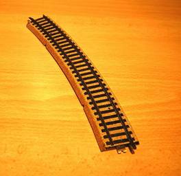
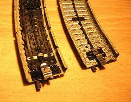
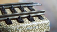
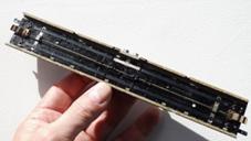
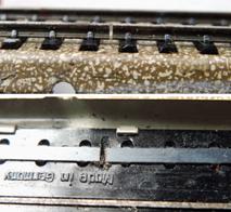
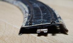
An interesting form detail of the
arches: The sheet metal track body has a 2
mm wide fold on the lower edges, on which the track rests on the table. We
know that from the older M-tracks. |
|
|||||||||||||||||||||||||||||||||||||||||||||||||||||||||||||||||||||||||||||
|
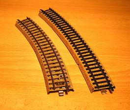
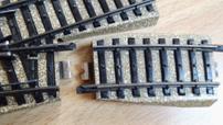
The difference to the M-rails is that
this fold has gaps. This makes it possible to raise the outer edge of the
arch by this 2 mm with little effort, to „exaggerate" the arch by
bending the fold back again. I found the track shown in a bundle. |
|
|
||||||||||||||||||||||||||||||||||||||||||||||||||||||||||||||||||||||||||||
|
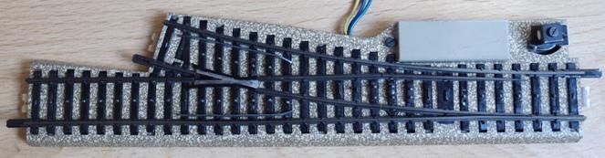
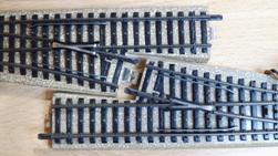
Now let's take a closer look at the turnouts: |
|
|||||||||||||||||||||||||||||||||||||||||||||||||||||||||||||||||||||||||||||
|
As mentioned, the turnouts have
solid profile rails. |
|
|
||||||||||||||||||||||||||||||||||||||||||||||||||||||||||||||||||||||||||||
|
The radius of the branch is 585 mm, the
curve angle is 3/4 of the normal „Modellgleis“ curve.
It doesn't get any shorter than this. This turnout design was only taken up
again by Märklin in 1975 with the M-track turnouts 5137 to 39. |
|
|||||||||||||||||||||||||||||||||||||||||||||||||||||||||||||||||||||||||||||
|
|
|
|||||||||||||||||||||||||||||||||||||||||||||||||||||||||||||||||||||||||||||
|
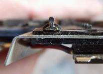
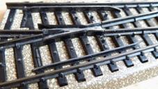
The guard rails (check rails) are
made of metal, very solid and, with a distance of approx. 2 mm from the stock
rail, significantly more effective than those on the M-track turnouts. |
|
|
||||||||||||||||||||||||||||||||||||||||||||||||||||||||||||||||||||||||||||
|
The turnout lantern is almost
identical to that of the M-track turnouts of that time. The cover of the solenoids is a
little ... unattractive. |
|
|
||||||||||||||||||||||||||||||||||||||||||||||||||||||||||||||||||||||||||||
|
The construction of the turnout
blades deserves special attention: |
|
|||||||||||||||||||||||||||||||||||||||||||||||||||||||||||||||||||||||||||||
|
Both tongues have their own pivot
bearings. This type of construction is still used today in German tram
turnouts. |
|
|
||||||||||||||||||||||||||||||||||||||||||||||||||||||||||||||||||||||||||||
|
The tongues are prototypically slimmed
towards the end, the stock rails have recesses to
accommodate the tongues. The tongues are moved by a slide in
the middle of the tongues where there is no sleeper. |
|
|||||||||||||||||||||||||||||||||||||||||||||||||||||||||||||||||||||||||||||
|
The shortness of the branching track
requires special adapters. The elaborate interior of the turnout prevents
such a simple solution as was chosen for the M-track turnouts 5137 to 39
(almost every track section fits there). |
|
|
||||||||||||||||||||||||||||||||||||||||||||||||||||||||||||||||||||||||||||
|
Two turnouts fit together with their
branching legs. The crossing of the „Modellgleis“ system
also fits directly to the turnout. |
|
|
||||||||||||||||||||||||||||||||||||||||||||||||||||||||||||||||||||||||||||
|
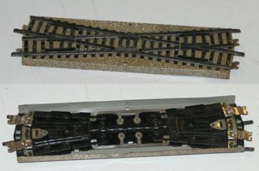
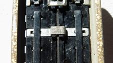
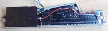
We now look at the turnout from
below: |
|
|
||||||||||||||||||||||||||||||||||||||||||||||||||||||||||||||||||||||||||||
|
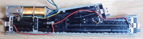
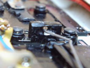
The drive is covered, as you are
used to with M-track turnouts.
The center conductors are mounted in
4 parts in the plastic insert and connected with a red wire. The metal contact area around the
frog is connected with a brown wire. The above-mentioned slide for moving
the tongues is moved by a simple rigid wire. The shape of the kinked wire
creates the movement of the slide. The elasticity of the wire allows the
switch to be cut open.
|
|
|||||||||||||||||||||||||||||||||||||||||||||||||||||||||||||||||||||||||||||
|
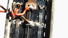
A simple
kinked wire, pushed straight through a hole ... ingeniously
simple. No spring that can wear out, break or get lost. |
|
|
||||||||||||||||||||||||||||||||||||||||||||||||||||||||||||||||||||||||||||
|
Conclusion: If one observes
the market with patience and common sense, the „Modellgleise“ can be acquired
at prices that have to be paid for new C‑track sections. Anyone
who is impatient or wants unmarked pieces can pay many times more. The
„Modellgleise“ are fully compatible with the M track system, but noticeably
more beautiful than this. Turnouts
and curves are unrivaled in the M-Track system. That is why they are the
first choice for me in the visible system area. There was also a Märklin
product insert. |
|
|||||||||||||||||||||||||||||||||||||||||||||||||||||||||||||||||||||||||||||
|
The Prototype Märklin-H0-Knowledge Layout-Building Modelstock |
|
|||||||||||||||||||||||||||||||||||||||||||||||||||||||||||||||||||||||||||||